Setting up Layer 2 Networking on Amazon EC2
Some workloads are strong candidates for moving to the Amazon Elastic Compute Cloud (Amazon EC2) but depend on Layer 2 (L2) network communication, which Amazon Virtual Private Cloud (Amazon VPC) doesn’t natively support. With the right approach, you can run these workloads on AWS. Layer 2 requirements appear in a few ways. Industrial control systems can use proprietary L2 protocols to communicate between their nodes. Legacy applications can rely on hard-to-change MAC addresses buried in configuration databases. Regulatorily validated environments can’t modify the software image without expensive re-certification. These workloads need broadcast, multicast, custom MAC addresses, or raw Ethernet frames to function.
In this post, you’ll learn why L2 traffic is a challenge, and explore four architectural patterns that provide L2 connectivity for your workload. Each option gives you different capabilities, which I summarize in a table at the end to guide you to the right pattern for your use case.
Prerequisites
To follow along with this post, you need:
- Familiarity with AWS, Amazon VPC networking, general Amazon EC2 instance usage, and the AWS Command Line Interface (AWS CLI) or the AWS Management Console
- An AWS account with permissions to launch Amazon EC2 instances and configure Amazon VPC networking
- For options 3 and 4: an instance type that supports nested virtualization (I use m8i.4xlarge for the examples)
- Basic Linux or Windows administration skills, depending on your chosen operating system
Why Layer 2 networking is a challenge on Amazon EC2
Amazon VPC is a Layer 3 network. The AWS Nitro System hypervisor validates Ethernet frame headers on every packet leaving an instance. The AWS Nitro System hypervisor permits the Elastic Network Interface (ENI) to pass only ARP, IPv4, and IPv6 through, and drops other frame types (including IEEE 802.3 (Ethernet) Logical Link Control (LLC), proprietary protocols, and raw Ethernet), before they reach the Amazon VPC network. Beyond EtherType filtering, Amazon VPC enforces additional constraints:
- The AWS Nitro System hypervisor validates source and destination MAC addresses against ENI registrations. Instances have an option to disable source/destination checks, but it disables only the check that the instance is either the source or destination IP address, not the MAC addresses.
- By default, an Amazon VPC does not forward broadcast and multicast frames between ENIs. You can support multicast by using AWS Transit Gateway, which addresses most cases that require multicast. No AWS native option does the same for broadcast frames.
- ENIs do not support promiscuous mode. An ENI receives only frames addressed to it.
These constraints mean workloads that depend on proprietary L2 protocols, NIC teaming with specific MAC addresses, heartbeat mechanisms, or promiscuous mode can’t operate directly on Amazon EC2. The following four options solve this problem at different levels of capability. This post uses the SoftEther VPN Project, an open-source cross-platform VPN system from the University of Tsukuba. You configure SoftEther either through configuration files or its vpncmd command line utility – the examples here use vpncmd throughout. You can use other similar projects if SoftEther does not meet your needs.
Option 1: Direct SoftEther tunnel between two hosts
The simplest configuration connects exactly two instances with a point-to-point SoftEther tunnel. One instance runs SoftEther Server with a Virtual Hub, and the other connects as a SoftEther Client. Figure 1 shows this architecture:
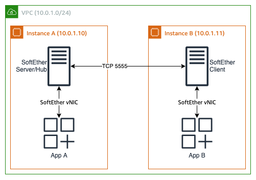
Figure 1: Two instances with SoftEther connected directly.
Instance A runs both the SoftEther Server (with a Virtual Hub) and the workload application. Instance B runs a SoftEther Client that connects to Instance A. Both applications bind to their local SoftEther virtual NIC, which places them on the same L2 segment through the tunnel. The Amazon VPC sees only a single TCP connection between the two instances.
After installing the server and client packages, you configure this deployment as follows. Note that you should replace (Your_Random_Password) with your own secure password. On Instance A (the hub):
On instance B:
This option works well if you need L2 communication between two instances and you can modify the OS on the instance. It works the same whether same-VPC, cross-VPC, Windows or Linux, or between AWS and outside of AWS – SoftEther encapsulates everything in a single TCP port 5555 connection.
Option 2: L2 overlay with SoftEther VPN (no nested virtualization)
When you need more than two instances, you must pick an instance to be the virtual hub. This can be one of the instances running the workload; however, I recommend using a separate instance for the SoftEther hub. This provides isolation between the workloads and the hub. You should restrict the hub instance to running only SoftEther, allow only TCP port 5555 in from expected clients by security group, and use AWS Systems Manager for administrative work on it. Because this instance performs only this role, you should size it for your workload – for lightweight use, an Amazon EC2 T-series instance works well here. Figure 2 gives an example.
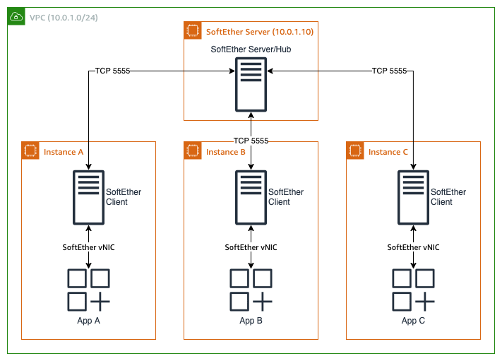
Figure 2: Three instances, separate hub configuration
Each instance runs a SoftEther VPN Client that connects to a central SoftEther VPN Server over a standard TCP connection (port 5555). As with Option 1, these instances can be anywhere with IP connectivity – while I show them all in a single Amazon VPC for illustration, that is not a requirement. The configuration for this is similar to Option 1 – you configure the server with the information about the clients, and then you point the clients to the server.
Server configuration:
Repeat the UserCreate and UserPassword set commands for each client. Then, for each client:
Option 3: Single-host nested VMs and Linux bridge
If your workload requires promiscuous mode, NIC teaming, or an unmodified OS image, nested virtualization on supported instance types (I use an m8i.4xlarge below) can solve this problem, potentially without SoftEther at all. On the instance itself, you can run your OS of choice – this solution works with both Windows and Linux bridging. I use Ubuntu 24.04 for the examples.
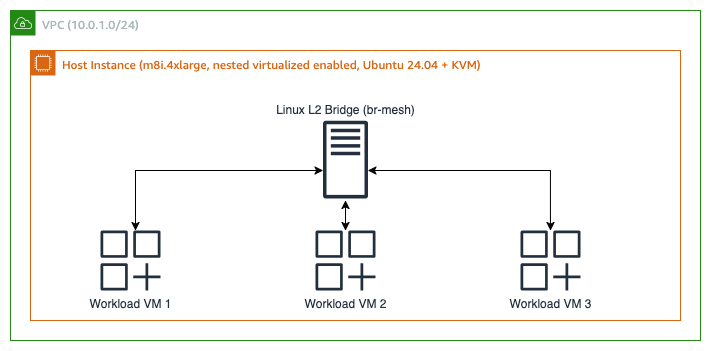
Figure 3: Using Linux bridging and nested virtualization
To start with this option (and option 4), you must create instances with nested virtualization. This option is off by default. If you use the AWS CLI to create the instance, you must add --cpu-options "NestedVirtualization=enabled" – specifying a supported instance type is not enough.
To configure this example, first install qemu-kvm and create the L2 bridge:
Then, import and configure a nested VM as usual. The following parameters are all for example purposes, except the bridge=br-mesh line – configure the rest as you need.
One common option is model=e1000e, which causes the nested VM to see PCI-bus standard NICs. This is a useful workaround for software that filters out virtual or non-physical network interfaces. Specifying the MAC address explicitly helps with software that needs manual configuration for target devices.
Option 4: Multi-host nested VMs with L2 tunnels
This option gives the most flexibility and capabilities, at the cost of requiring the most setup work.
If your workload must span multiple Amazon EC2 instances because of size, redundancy, or other reasons, and still requires full L2 fidelity, combine nested virtualization with a SoftEther Bridge to extend the L2 domain across hosts. Each host instance runs a hypervisor (KVM or Hyper-V) with nested VMs connected to a local virtual switch, and the SoftEther Bridge joins that switch to a central SoftEther hub, creating a single broadcast domain that spans all hosts.
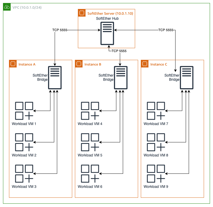
Figure 4: Multiple nested virtualized instances tied together with a SoftEther hub
For each host instance, you start with creating a local bridge and then tie SoftEther to it. For Linux:
For Windows PowerShell:
You can then attach the resulting network to your nested VMs.
Improving resiliency with a second SoftEther hub
Options 2 and 4 show a single SoftEther hub. For higher redundancy, I recommend adding a second instance, in a second Availability Zone, to gain the advantages of a well-architected, highly resilient design.
To do this, deploy two SoftEther Server instances, called SE-Server-A and SE-Server-B, each with its own Virtual Hub. On each hypervisor host, run two SoftEther Bridge or Client instances — one cascading to SE-Server-A, the other to SE-Server-B. Create two separate virtual switches on the hosts, each bridged to its respective SoftEther Server. For option 2, attach your workload to both NICs. For option 4, attach each nested VM to both virtual switches with separate NICs. In both options, you must use workload-specific capabilities, such as NIC teaming or bridging, to support failover and redundancy.
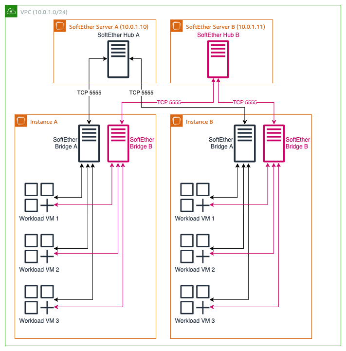
Figure 5: Dual SoftEther Server Redundancy
Using this method, if one hub fails, needs updating, or has an impairment, traffic fails over to the path through the other hub. The nested VM sees a brief link interruption on the NIC facing the failed hub, and the bonding driver redirects all traffic to the working one. When the failed hub recovers, the bond rebalances automatically.
Implementation Notes
- For workloads using layer 2 Ethernet to carry non-IP traffic, configure the hub as follows to pass them:
- Workloads that require broadcast might need to adjust broadcast storm control detection:
- For options 3 and 4, if you use Windows as the outer hypervisor, Hyper-V might need MAC spoofing turned on for the nested VMs:
Monitoring and troubleshooting
For the SoftEther options, here are commands I found useful for monitoring and troubleshooting while working on this post:
- Check session status
- View learned MAC addresses
I recommend you also be familiar with SoftEther’s troubleshooting guide. For options 3 and 4, if your host OS says it can’t start nested VMs, verify you specified --cpu-options "NestedVirtualization=enabled" when you created the instance, or have turned it on from the AWS Management Console. Changing this setting requires stopping the instance, changing the flag, and restarting it.
Cleaning up
To avoid incurring future charges, delete the resources you created for this walkthrough:
- Terminate the Amazon EC2 instances you launched (SoftEther hubs and workload instances).
- Delete any security groups you created specifically for SoftEther traffic.
- Remove any additional ENIs no longer attached to running instances.
How to choose a layer 2 connectivity option
| Feature | Option 1 | Option 2 | Option 3 | Option 4 |
| Number of workloads supported | 2 | As many as you can run on multiple Amazon EC2 instances | As many as can run on one Amazon EC2 instance | As many as you can run on multiple Amazon EC2 instances |
| Non-IP frames | Yes | Yes | Yes | Yes |
| Custom/fixed MAC addresses | Yes | Yes | Yes | Yes |
| Broadcast and Multicast | Yes | Yes | Yes | Yes |
| Promiscuous mode | No | No | Yes | Yes |
| Presents a “real” physical NIC | No | No | Yes | Yes |
| Requires modifying the workload OS image | Yes | Yes | No | No |
| Requires the use of SoftEther | Yes | Yes | No | Yes |
Conclusion
In this post, I showed why Layer 2 traffic doesn’t pass natively between Amazon EC2 ENIs, and walked through four patterns that provide Layer 2 connectivity for your workloads. The launch of nested virtualization has opened up additional options, including patterns that don’t require modifying the workload OS image (beyond adjusting the network interfaces, as needed). Use the comparison table to choose the pattern that fits your requirements. To explore further, refer to the following resources:
Using the techniques discussed here, you have a solid route for migrating workloads that require custom or unusual Layer 2 connectivity into AWS. If you have questions or would like to comment or discuss this post, start a new thread on AWS re:Post or contact AWS Support.
About the authors

Andrew Gray
Andrew Gray is a Principal Solutions Architect at AWS, specializing in networking architecture and engineering. With experience as a lead networking engineer in telecommunications and higher education, Andrew enjoys applying his technical expertise to develop innovative cloud solutions. He is passionate about solving complex challenges at the intersection of networking, infrastructure, and code.